
SMC-Roe Schlyer 22'x30" Tunnel Washer (Rodent,bedding, & Lab Cage) - Reno,NV.
SMC-Roe Schlyer 22'x30" Tunnel Washer (Rodent,bedding, & Lab Cage) - Reno,NV.
$9,600 (USD)
Location:
or
Call +14158277832
Description
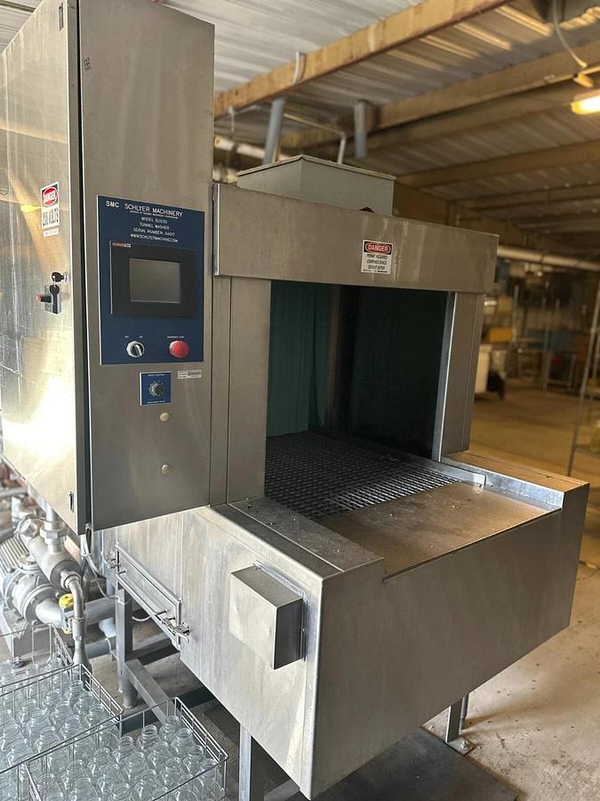
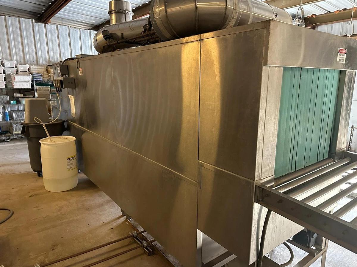
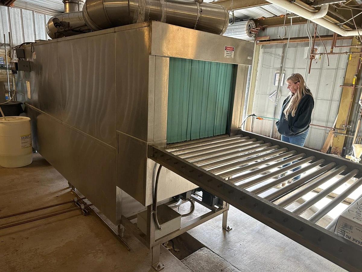
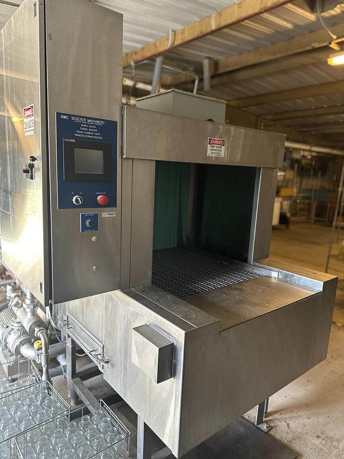
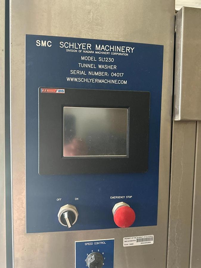
Schlyer SL1230 Tunnel Cage Washer System
smc roe
Model SL1230
22' Length
30" wide stainless belt
=====================================
VIN/Serial: 04017
-----
Weight 5000 Pounds
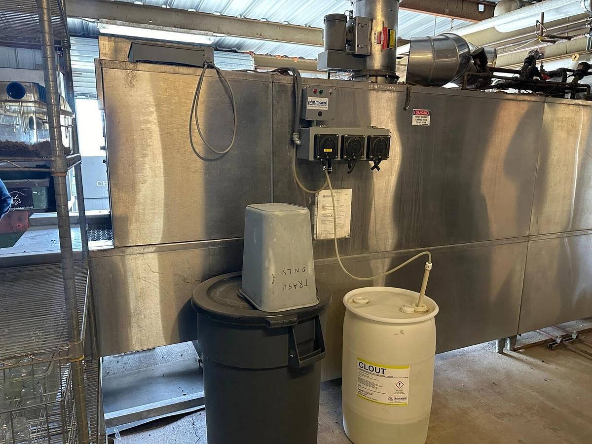
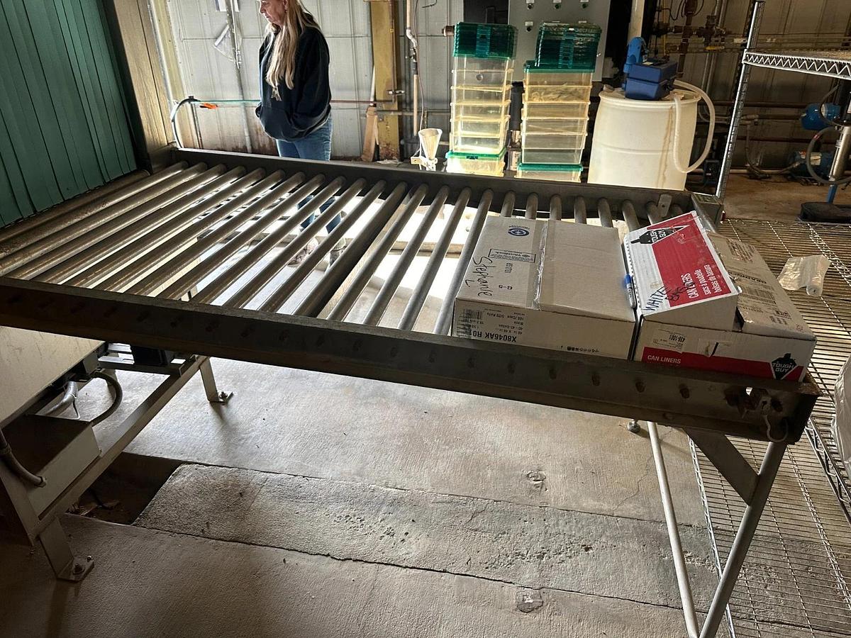
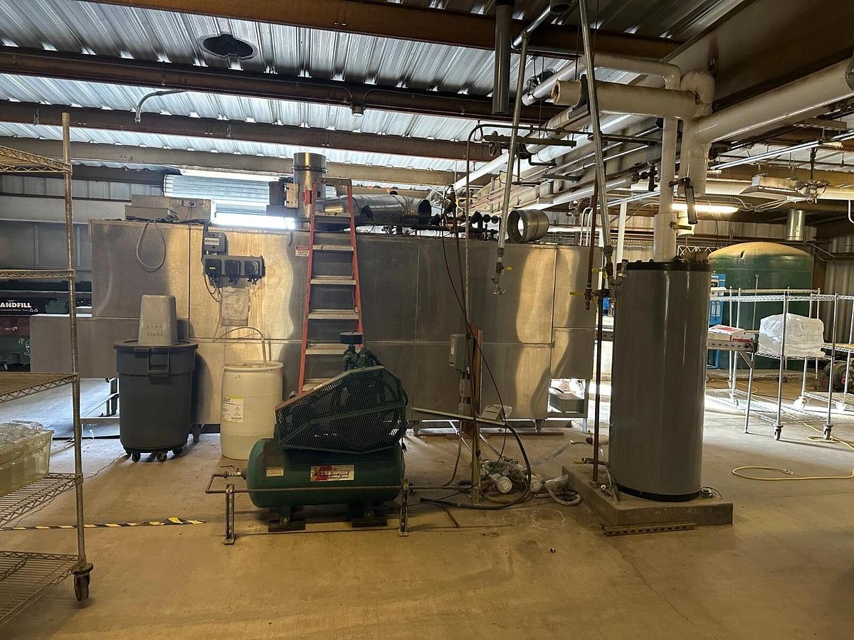
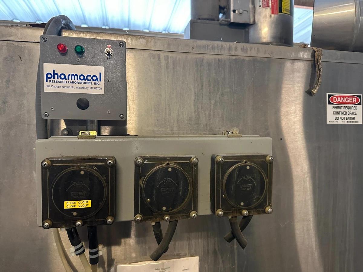
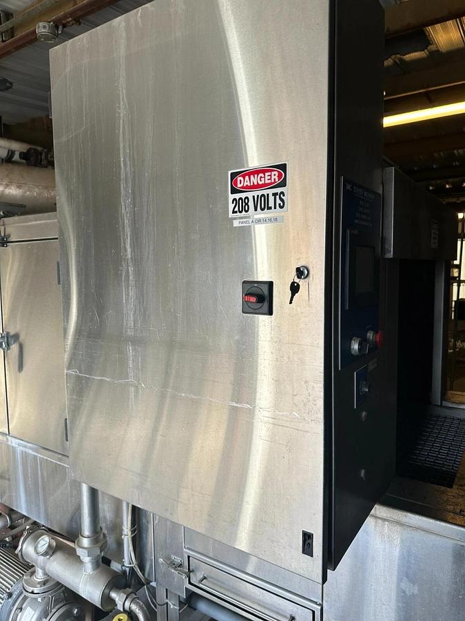
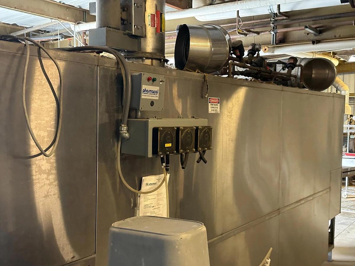
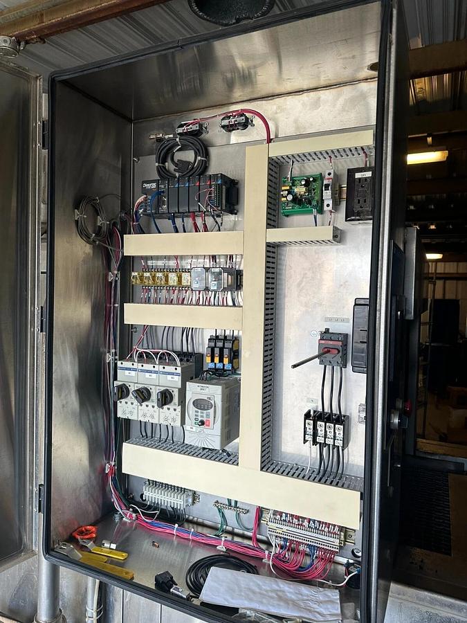
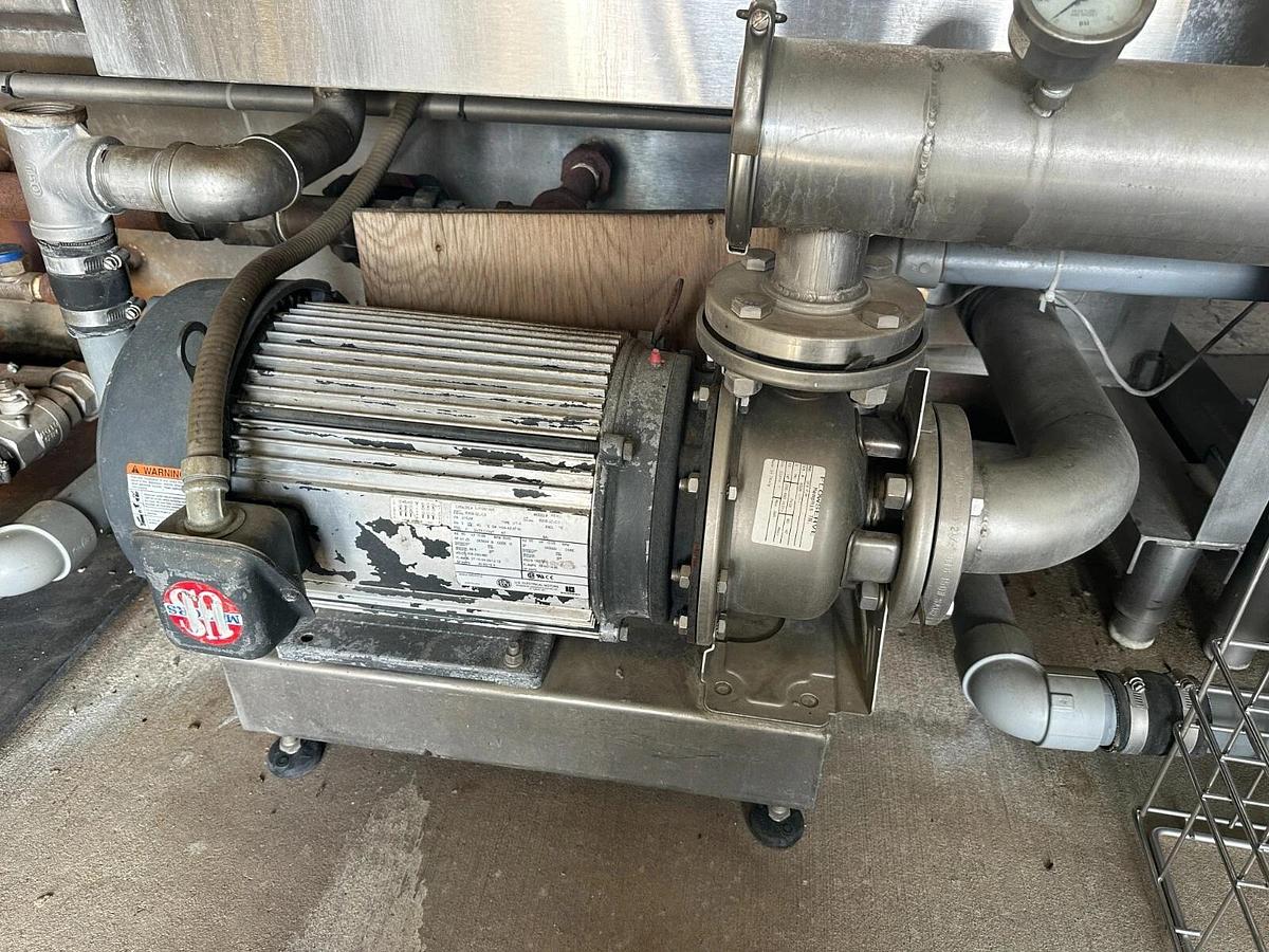
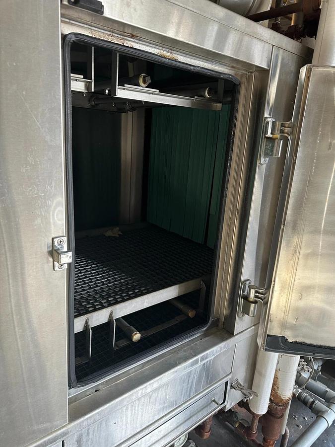
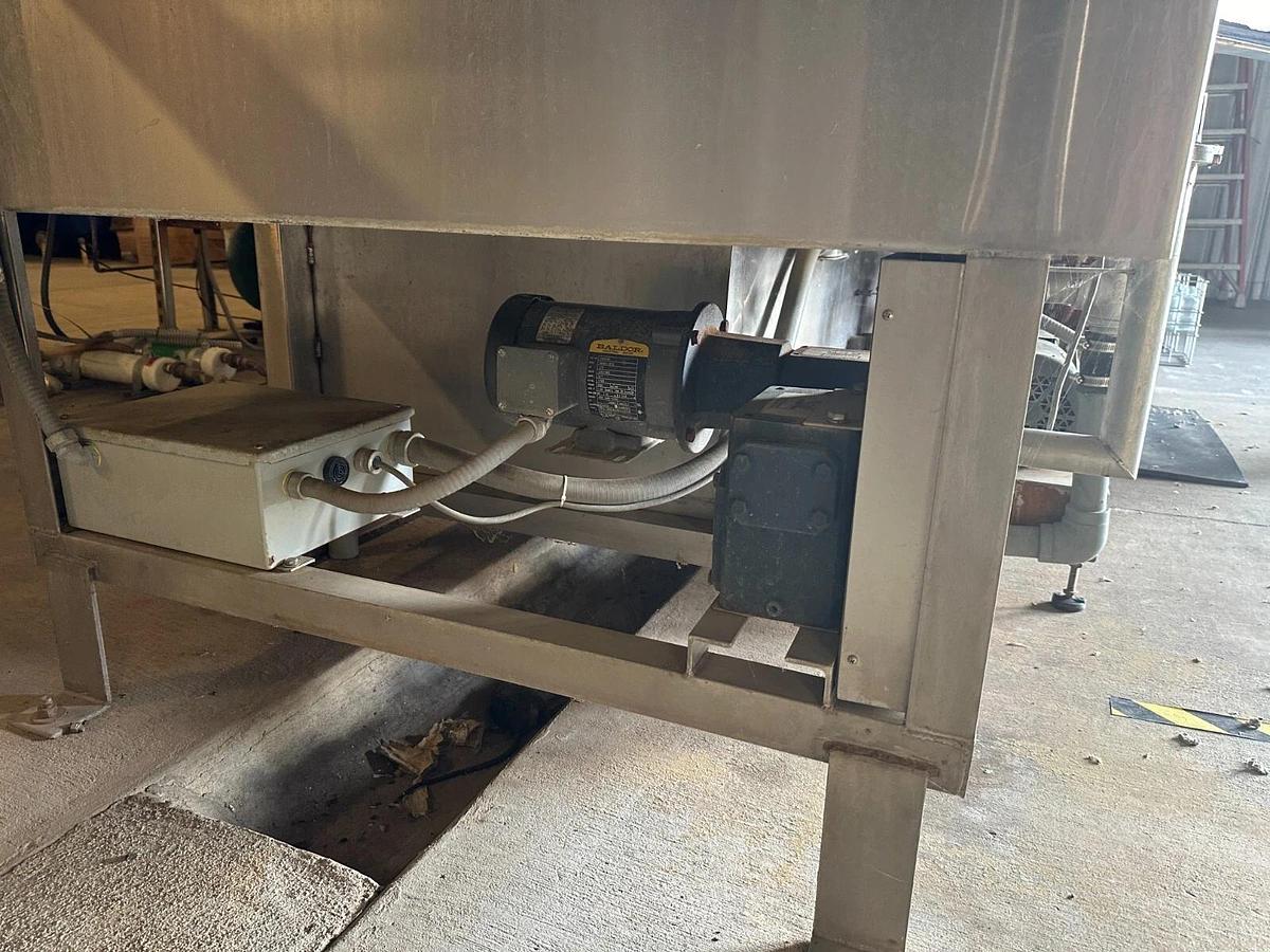
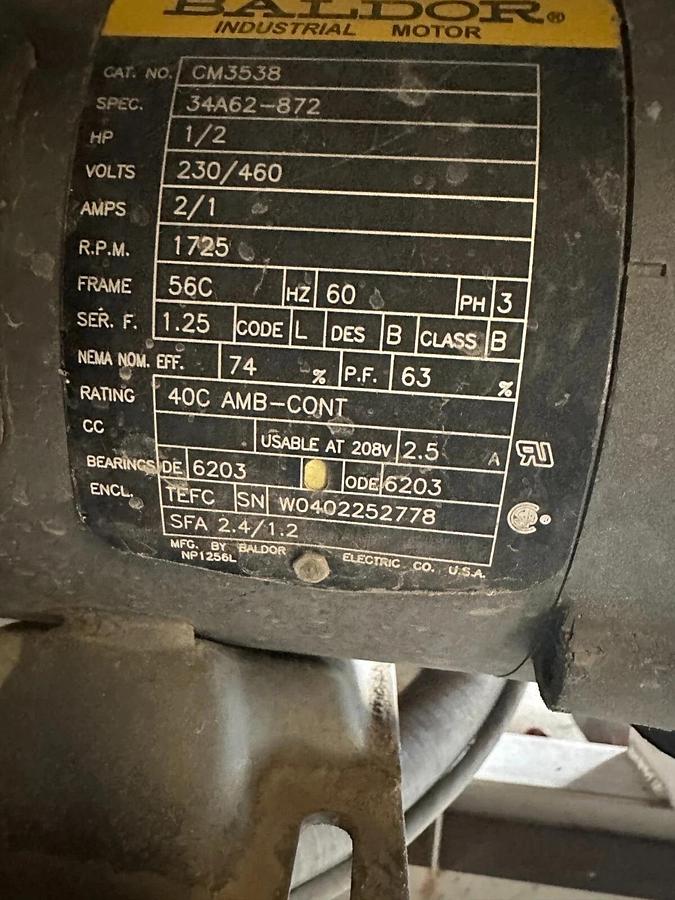
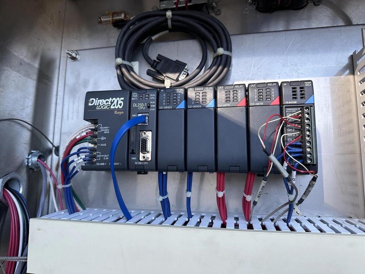
Includes SL1230 Stainless cage wash unit ,drying rack, all controls, pumps.
Item is now disconnected from power and ready for pickup.
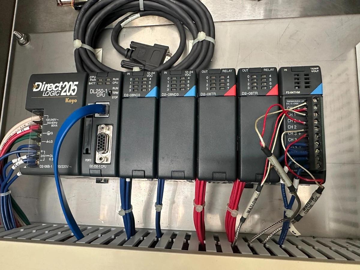
direct Logic 205 koyo automation control
FREE "Hotshot" LOADOUT !!
Item located at my warehouse:
Mound House, NV 89706
This appears to have had very minimal use.
Replacement Cost Approx $122,500
Delivery possible.
I also have many IVC's and other rodent related equipment available.
Just ask !
=====================================
Please include your "Zip+4" with any inquiries so I can get you the absolute lowest freight quote.
=======================================
From Manufacturers Flyer:
" SMC Model SL1200 Engineering Specification Page 1 of 12
Model SL1200 Tunnel WasherGeneral Specifications1.0 General DescriptionThe Model SL1200 Tunnel Washer is a high capacity conveyorized spray washer capable ofprocessing any items which can be placed inside the washing compartment. It is specificallydesigned to clean and sanitize animal cages, pans, water bottles and other items ancillary to the careof laboratory animals. Several sizes are available, as well as many optional features. The ModelSL1200 incorporates a large number of âstate-of-the-artâ features to ensure thorough, efficientcleaning, as well as many features unique to our design.2.0 DimensionsModel SL1224 Model SL1230 Model SL1236 Model SL1248Belt Width 24â 30â 36â 48âTunnel - Inside* 25âW x 25âH 31âW x 25âH 37âW x 25âH 49âW x 25âHOverall 41âW x 83âH 47âW x 83âH 53âW x 83âH 64âW x 83âHLength 22âL 22âL 22âL 22âLDryer SectionIncluded in Length7âL 7âL 7âL 7âL*Note: Dimensions are maximum chamber opening sizes. Actual Load size must be smaller toallow for clearances. Custom chamber sizes, lengths and widths can be provided as required.3.0 Spray Headers3.1 Spray headers shall be supplied and equipped with machined jets. Jets shall deliver a solidelliptical spray pattern for optimal impact to the load. No rotating spray arms shall be utilized.3.2 Individual spray headers shall be connected to supply manifolds by means of slip-fitcouplings which shall prevent undue leakage yet shall allow headers to be removed with one handand no tools.3.3 Design of the header mounts shall prevent any individual header from being installedincorrectly or in the wrong space. SMC Model SL1200 Engineering Specification Rev. 031914 Page 2 of 123.4 Balanced Spray Hold-Down System3.4.1 Headers shall be equipped with throttle valves which shall allow the upper and lowersprays to be balanced such that any items placed upon the belt shall be held down by the force of theupper sprays. At start-up, factory technical personnel shall balance the sprays and set the system tooperate correctly and efficiently with all items in the owner's inventory/4.0 Solution Strainers4.1 Wash solution shall be pumped through a specially designed strainer that ensures that thewash spray jets shall not be plugged by entrapped debris.4.2 Strainer shall be designed with orifices significantly smaller than those in the jets, such thatdebris which is suspended in the treatment fluids and which could lodge in the jet orifices shall betrapped prior to delivery to the header system.4.3 At selectable, timed intervals any particles that have been trapped shall be automaticallyflushed to drain.4.4 Strainer shall be removable with no tools via a sanitary-style clamp. System shall becompletely self-regulating and require routine inspection and maintenance no more than once perweek.4.5 In addition to the Self-Flushing wash solution strainer, each treatment station shall beequipped with an oversized drawer-type screen which will prevent large debris from entering therecirculation tanks or the drain.5.0 Automatic Temperature Regulation and Guarantee5.1 The Final Rinse, Rinse and/or Wash treatments shall be selectable as GuaranteedTemperature Phases.5.2 Drive belt shall not run until the solution temperature of a selected treatment phase hasreached the set point (typically 180 degrees F or higher), thus ensuring that the load has been subjectto the proper temperature for the entire phase duration. If the temperature drops below the set point,the drive belt will momentarily pause to allow the temperature to stabilize.5.3 Failure of any Guaranteed Temperature Phase to reach the setpoint temperature within theallotted time shall result in a Fault Condition. (Temperature Failure; see par. 6.7.4)6.0 Safety and Certifications6.1 An OSHA-style Emergency Stop button shall be installed on the operator control panel andat the exit end of the machine. These switches shall be wired to a hard-wired safety stop relay,which when de-activated shall interrupt all power to the outputs of the machine, thus satisfyingOSHA standards for industrial machinery. SMC Model SL1200 Engineering Specification Rev. 031914 Page 3 of 126.4 Magnetic safety switches on the doors shall reliably ensure that all treatments stop instantlyif any door is opened.6.5 All outputs external to the electrical box shall be low voltage DC, Intrinsically Safe bythe definition of OSHA and NEC.6.6 All devices and components which consume electrical power shall be UL listed and/orapproved, and shall bear NEMA, IEC or other recognized International ratings appropriate forthe use intended. The control assembly shall be produced in a UL Panel Shop and shall be ULListed according to UL 508(A) standards.6.7 Fault Conditions shall be annunciated on the operator interface screen, and shall be sentto the RS232 interface port for printing or data acquisition. At least four (4) fault conditions shallbe so identified.6.7.1 Emergency Stop- Depression of the Emergency Stop Button shall reset themachine and display a fault message which identifies the source of the emergency stopsignal.6.7.2 Door Open- Lack of positive door closure shall cause the machine tocease operation. Fault message shall indicate which door is at fault.6.7.3 Heat Fault- Failure of any Temperature Guaranteed Phase to reach thedesired temperature in the expected time shall cause the machine to cease operation andthe screen to display the appropriate Heat Fault message.6.7.5 Fill Fault- Fill Fault message shall be displayed and machineoperation shall cease if any tank fails to fill in the allotted time.7.0 Pneumatically Operated Valves7.1 All automatic ball valves shall be controlled by Pneumatic operators. Electric-motoroperated ball valves shall not be acceptable.7.2 All automatic water and steam control valves shall be direct-operated pneumatic types.Pilot-operated solenoid valves or any valve which incorporates a diaphragm-type sealing systemshall not be acceptable.8.0 Microprocessor Control8.1 The treatment schedule and all other machine functions shall be controlled by a readilyavailable, non-proprietary, industrial style modular programmable controller such as thatmanufactured by Koyo and sold throughout the United States by Automation Direct.8.2 Module replacement for the I/O system shall be easily accomplished with no tools and nowiring disconnection or connection. SMC Model SL1200 Engineering Specification Rev. 031914 Page 4 of 128.3 The control system shall be programmed in simple ladder logic.8.4 A Color Touch Screen shall provide complete operator interface, diagnostic andprogramming capability. No special skills or knowledge shall be necessary to set up and controlall machine functions.8.5 Diagnostics shall be available from the Color Touch Screen which will allow directaccess to all I/O points for complete diagnosis of all machine systems.8.6 Treatment schedules and cycle phase selections shall be programmable from the Screen,and PIN screens shall be available at the discretion of the supervisor to lock out access to thecycle phase programming functions. All timers in the program, as well as all cycle phasetemperatures, shall be accessible and settable through the operator interface screen, with nonecessity for the connection of either an auxiliary programming device or a modem/telephoneline connection.8.7 All controls shall be of industrial design and type, in order to resist the extremeenvironmental demands of the washroom. All electrical wiring, operator interface controls andcircuits shall be protected in accordance with NEMA, UL and NEC standards.9.0 Insulated Exterior9.1 The exterior of the machine shall be fully insulated with 2" of rigid insulation covered by aStainless Steel jacket for protection. This insulation shall be an integral part of the machine,designed to maintain the high temperatures required in the treatment chamber and to limit radiationloss to the surrounding air.10.0 Positive Door Gasketing10.1 The doors shall be sealed with long-life, durable gaskets, which will ensure that vaporleakage around the door is minimized. The gaskets shall be easily replaceable with no tools.Labyrinthine seals or other gasket-less methods which allow vapor to escape shall not be utilized.11.0 Welded Construction11.1 All body joints below the overflow point shall be welded. If site conditions necessitate asectionalized shipment, factory installation personnel shall field weld all tank joints to ensureintegrity of the tanks and cabinet. Gasketed joints below the water overflow point shall not beacceptable.12.0 Manuals & Documentation SMC Model SL1200 Engineering Specification Rev. 031914 Page 5 of 1212.1 A full set of manuals explaining machine operation and PLC operator controls shall beprovided.12.2 A hard copy of the PLC ladder diagram shall be available at no additional charge.12.3 A complete list of purchased parts including original part numbers, where the parts werepurchased, and the nearest local distributor where the parts can be purchased shall be provided asa standard part of the manual. All purchased machine components such as jets, valves, PLCmodules, pneumatic system parts, etc., shall be entirely non-proprietary and available forpurchase freely and widely through normal industrial supply outlets.20.0 Machine Operation20.1 Items to be cleaned shall be placed onto the belt by the operator. Items so placed shall beconveyed through each treatment in turn. Once items appear at the unload end of the machine, theyshall be removed by the operator.20.2 All cycle phase selections and other cycle options shall be available for selection from theColor Touch Screen, with optional supervisory PIN screens preserving security of standard cyclephase information. Machine memory shall allow storage of at least four (4) distinct cycles, to berecalled through simple screen selections.20.3 Standard cycle phases shall consist of:20.3.1 Pre-rinse - Water salvaged from the rinse treatment phase shall be sprayed onto theinside surfaces of the load in order to flush excess debris from these surfaces prior to loadentering the wash treatment chamber. Spent water shall be conducted to drain through alarge drawer-type strainer.20.3.2 Wash - Detergent solution shall be sprayed over all surfaces of the load, underpressure from the main wash pump. All solution shall be strained through the drop screenand the self flushing debris strainer before being conducted to the jets. Temperature of thedetergent solution shall be maintained at the desired setpoint, up to 190 degrees F, by thefully submerged sump steam coil.20.3.3 Rinse - Rinse water shall be sprayed over all surfaces of the load, under pressurefrom the rinse pump. Rinse solution shall be strained through the drop screen before beingconducted to the jets. Temperature of the rinse solution shall be maintained at the desiredsetpoint, up to 190 degrees F, by the fully submerged sump steam coil.20.3.4 Final Rinse - Fresh hot water from the customer's hot water supply shall be sprayedover all load surfaces at a guaranteed set point temperature up to 205 degrees F, thusensuring proper sanitation and adherence to AALAC guidelines.30.0 Details of Construction SMC Model SL1200 Engineering Specification Rev. 031914 Page 6 of 1230.1 General30.1.1 All wetted parts shall be of Type 304 Stainless Steel or appropriate polymericmaterials.30.1.2 All electrical assemblies, piping assemblies and mechanical apparatus shall bedesigned for, and be appropriate for use in, a high temperature sanitary wash-downenvironment. All components shall be selected for their ability to perform for long periodsof time in the adverse and high production environment of the laboratory washroom. Eachpurchased part and each engineered part and sub-assembly shall be scrutinized and allspecific design decisions shall be made in the light of these basic criteria.30.1.3 All purchased components shall be un-modified, off-of-the-shelf items available tothe owner in his locality, should he need them.30.1.4 Original manufacturers' part numbers and descriptive information for all purchasedparts shall be made an integral part of the service manual information provided at time ofinstallation, and every effort shall be made throughout the life of the machine to assist theowner in acquiring any parts needed.30.2 The cabinet, tanks and supports shall comprise one welded assembly. The tanks shall beconstructed of 12 gauge T304 Stainless Steel, and the upper cabinet shall be 14 gauge T304Stainless. All exterior finishes shall be #3, fully polished. The top and sides of the machine shallbe fully insulated with a 2" thick blanket of rigid fiberglass, completely enclosed in a 20 gaugeT304 Stainless jacket with #3 polished exterior. Adjustable legs of sanitary design shall beprovided for leveling. Stainless and Neoprene Rubber baffles between sections shall minimizetreatment solution carry-over.30.3 The doors of the washer shall be of double-walled stainless steel construction, 2" thick, andfilled with insulation. The door hardware and gaskets shall ensure that there are no significant leaksof solution or vapor during normal operation. Door safety switches shall ensure that the machinecannot operate with the doors open.30.4 Conveying surface shall consist of a Stainless Steel flat wire belt of at least 11 gaugethickness, tensioned by catenary sag and requiring no belt tensioning devices. Sprockets shall beused at both ends of the belt to ensure consistent tracking. Belt shall be supported by a system ofStainless Steel runners which will provide extreme long and trouble-free life. No replaceable wearstrips shall be acceptable. Belt shall be driven by an AC Variable Speed Motor and inverter,selected to allow operator selection of belt speeds from ~4 fpm to ~10fpm. Belt speed shall beadjustable from the Color Touch Screen Interface, behind a PIN security screen.30.5 The wash and rinse tanks shall be equipped with stainless steel steam coils, fully welded inaccordance with ASME Section VIII standards for Unfired Pressure Vessels and fabricated fromStainless Steel materials designed to carry steam at the rated pressures. No structural parts will beacceptable. The coils shall be easily removed for cleaning or maintenance. SMC Model SL1200 Engineering Specification Rev. 031914 Page 7 of 1230.6 Temperatures shall be controlled directly by the PLC. Temperature sensors shall be Type JThermocouples, connected directly to the analog inputs of the PLC and requiring no periodiccalibration.30.7 Steam controls shall be included for 30-80 psi dry steam. No diaphragm-type steam valvesshall be acceptable. Condensate traps shall be disc/thermodynamic type only.30.8 Water level shall be maintained by electronic level controls with removable and easilycleaned probes. Probes shall be removable for cleaning with no tools required, such as with asanitary-type clamp fitting.30.9 The treatment pumps shall be horizontal, close coupled pumps equal to a Flowserve ModelD824. Mechanical seals shall be carbon ceramic and Stainless Steel. No vertical or seal-less pumpsshall be acceptable.30.10 Spray jets shall be elliptical pattern spray jets equal to Spraying Systems Co.H1/4USS80XX. No proprietary jets shall be acceptable.30.11 Final Rinse heat exchanger shall be of 100% stainless steel, brazed or sintered plate design.No iron, copper or other material shall be acceptable. No shell-and-tube or helical flow design shallbe acceptable. Temperature regulation shall be provided by a Modulating Steam Valve, controlledby a PID loop running on the main PLC. Temperature shall be set by supervision as high as 205F,and shall be regulated within +/-4F.30.12 Washer programmable control shall provided by a modular industrial-type programmablelogic controller, programmed in ladder logic and replaceable and programmable by the customer'sown personnel if necessary. No proprietary control will be acceptable. All wiring and control shallbe per National Electric Code and all devices utilized shall be UL, NEMA and/or IEC-rated. Alloperator controls or devices shall be of standard industrial NEMA-rated types, chosen for theirability to operate over the long haul in the tough and corrosive environment of the washroom.Operator interface shall be a color touch screen. Control assembly shall be UL Listed and solabeled. 30.13 Discharge Cooling - Non Monitored: Washer shall be provided with an integral cool-downapparatus which shall ensure that all effluent is cooled to 140 degrees F. or less before gravityconduction to the customer's drain. This shall be accomplished by mixing the effluent with coldwater from the owner's supply. 30.14 Dryer System: An insulated stainless steel dryer section, 7â long, shall be provided. Dryershall be equipped with a dual drying system, having both an air knife for the outsides of thecages and a recirculating hot air dryer for the insides. The recirculating section shall be equippedwith stainless steel air discharge nozzles mounted in a stainless steel plenum. The nozzles shallbe calibrated to achieve optimum drying after all air and exhaust controls have been set. Air shallbe moved by a 5 H.P. heavy-duty blower with quiet, backward-inclined vanes, and shall circulate SMC Model SL1200 Engineering Specification Rev. 031914 Page 8 of 12heated air through a steam heat exchanger. This air shall be circulated over all surfaces of thecages at a temperature of up to 230 degrees F to ensure even and thorough drying. The air knifesection shall be equipped with a 10 HP regenerative blower capable of providing a high-velocitystream of air which will strip all water droplets from the outsides of the cages passing underneaththe knife. Knife height shall be adjustable by the operator from the Touch Screen Interface,which shall continuously indicate the current height of the knife.30.15 MATERIALS OF CONSTRUCTIONItem Materialbase Angle Iron, 304 SS, mill finishdoor panels 16 gauge, 304 SS - #3 finishside and top panels 14 gauge, 304 SS - #3 finishtank panels 12 gauge, 304 SS - #2B finishrecirculating piping Stainless Steelspray headers Stainless Steelrecirculating pumpshousing and impellerStainless Steelrecirculating valves Stainless Steelexternal water piping coppersteam coils Sch 40. 304 SS - #2B/mill finishinternal steam piping stainless steelexternal steam piping schedule 40 black irontemperature booster 304 SSdrain piping 304 SS and Sch 80 (C)PVCbarrier walls 20 gauge, 304 SS - #3 finish40.0 Optional Features40.1 Knocked-Down Shipment: Machine shall be provided in knocked-down condition, allpieces sized to suit the specific site, for reassembly at the customer's site. All joints whichare below the overflow point shall be fully welded. No bolted gasketed joints shall beacceptable below the water line. No special lifting equipment of any kind shall be requiredto move or set the equipment portions in place.40.2 Printer: A panel-mount printer with paper take-up shall be supplied to document allmachine parameters and faults. Print interval shall be settable by supervisory personnel.40.3 Unload End Powered Conveyor: The dryer belt shall emerge from the machine andform a powered unload section. Length of this section shall be specified by the owner,with four (4) feet being the default standard length.40.4 Conveyor Full Sensor: A photoelectric eye assembly shall be mounted at thedischarge point of the washer or the optional discharge conveyor. Whenever this sensor isblocked, belt operation shall be paused to allow the operator to remove the items from the SMC Model SL1200 Engineering Specification Rev. 031914 Page 9 of 12belt. An adjustable time delay is provided to allow items to pass through the eyemomentarily without interruption of belt operation. This feature shall ensure that no loadscan inadvertently fall off of the end of the conveyor.40.5 Stainless Steel Exhaust Fan: A Stainless Steel tube-axial-type exhaust fan shall beprovided to ensure proper ventilation in applications where the existing air handling systemsare inadequate or over-taxed.40.6 Windows: Tempered Safety Glass windows shall be provided in anydoors to allow visual inspection of the interior with the door(s) closed.40.7 Illuminated Interior: Machine shall be equipped with fluorescent strip lightassemblies which shall be mounted outside the machine above the roof. Tempered glasswindows shall be placed in the roof panels to allow light from the fixtures to enter themachine. Lights mounted interior to the machine shall not be acceptable.40.8 Discharge Cooling: Monitored: Washer effluent shall be conducted to astainless steel holding tank. A probe shall sense the discharge temperature and add therequired amount of cold water from the owner's supply to lower the discharge temperatureto below 140 F before discharging to the building drain system. The entire system shall beunder the supervision of the machine PLC control.40.9 Barrier Flanges for Recessing through One Wall: Stainless Steel Flanges shall beprovided to fully enclose the recessed end of the unit from wall to wall and floor to finishedceiling.40.10 Barrier Flanges for Recessing through Two Walls: Stainless Steel Flanges shall beprovided to fully enclose the âcleanâ and âsoiledâ ends of the unit from wall to wall andfloor to finished ceiling.40.11 Treatment Solution pH Neutralization System: Monitored: A monitored proportionalsystem shall be provided to automatically inject user supplied neutralization agent into thetank to neutralize acidic solutions before discharge to drain to conform to plumbing coderequirements. A probe shall sense the pH of the treatment solution and a proportionalamount of agent shall be injected to attain a neutral pH. A low agent reservoir level shall beannunciated to the operator.40.12 Automatic Tank Drains: The wash and rinse tanks shall be provided with automaticprogrammable valves located at the low points on the tanks. When each valve isactivated, the tank solutions shall be automatically dumped to gravity drain. The drainvalve shall operate at the pleasure of the operator.40.13 Descaling System: A programmable descaling system shall be provided whichwhen operated will remove scale buildup from the interior surfaces of the chamber.40.14 Seismic Restraints: Properly designed and attached seismic restraints shall beprovided to comply with local codes. SMC Model SL1200 Engineering Specification Rev. 031914 Page 10 of 1240.15 Remote Access Programming Capable: A modem or Ethernet connection shall beincluded in the modular PLC package to provide for Direct Factory AccessibleProgramming. This option shall allow trained SMC technicians to directly access theprogramming of the machine from a remote location for changes or diagnostic purposes.A dedicated analog phone line or an Internet connection shall be provided by the owner ifthis option is selected.40.16 Integral Air Compressor: An integral air compressor shall be provided to operate thedrive and pneumatic valves. This option shall be chosen whenever compressed air is notavailable from building utilities.40.17 Special Spray Configurations: Sprays shall be provided in various specialconfigurations in order to adequately clean any troublesome items in the owner's inventory.40.18 Special Cabinet Size: Cabinet shall be supplied in the exact shape and sizespecified to suit the owner's special needs.40.19 Low Steam Pressure: The unit shall be designed for a steam pressure below 30 PSI.All coils, valves, pipes and other devices shall be sized to operate under the conditionsspecified.40.20 Integrated Bedding Dispenser: An automatic bedding dispenser, SMC Model BD30,shall be integrated and attached to the discharge end of the unit. The BD30 series automaticbedding dispenser shall automatically dispense bedding into cages as the cages passthrough the filling chamber on a powered conveyor. Cages shall be automaticallytransferred and inverted to the bedding dispenser conveyor directly from the washer. Theamount of bedding needed per cage shall be adjustable and the unit shall accommodatevarious types of bedding materials.40.21 Integrated Bedding Disposal Unit: A bedding disposal unit shall be integrated with thewasher at the infeed end. Cages shall be manually dumped and/or scraped into the gratedarea of the unit, whereupon all debris will be ground and flushed to the drain. Controlsshall be fully integral with the wash unit controls. Separate controls for the grinder unitshall not be acceptable. Disposal unit shall be equipped with a manual rinse wand on aflexible connection. Grinder portion shall be of Stainless Steel construction and shall beequal to Insinkerator Model SS500.60.0 Utility RequirementsSL1224/SL1230 SL1236 SL1248Electrical 3ph, 60hz, 27 HP 3ph, 60hz, 30 HP 3ph, 60hz, 35 HPSteam 2 1/2 FPT 2 1/2 FPT 3 FPT30-80 PSI 30-80 PSI 30-80 PSI1800#/Hr 2000#/Hr 2400#/Hr SMC Model SL1200 Engineering Specification Rev. 031914 Page 11 of 12Condensate 1 FPT 1 FPT 1 FPTHot Water 1 FPT, 35 PSI 1 FPT, 35 PSI 1 FPT, 35 PSI120-180 Deg. F. 120-180 Deg. F. 120-180 Deg. F.6-8 gpm 6-8 gpm 8-10 gpmDrain 2 FPT 2 FPT 2 FPT140 Deg. F. Max 140 Deg. F. Max 140 Deg. F. Max10 GPM 10 GPM 12 GPMExhaust 12" Dia. 18" Dia. 18" Dia.1200 SCFM 1800 SCFM 2200 SCFM180 Deg Saturated 180 Deg Saturated 180 Deg SaturatedCompressed 1/2 FPT, 80 PSI 1/2 FPT, 80 PSI 1/2 FPT, 80 PSIAir 2 SCFM 2 SCFM 2 SCFMCold Water 3/4 FPT, 35 PSI 3/4 FPT, 35 PSI 3/4 FPT, 35 PSI3-4 GPM 3-4 GPM 4-5 GPM60.1 Notes to Utilities Table60.1.1 A disconnect switch shall be installed by others than SMC in accordance with allNEC and local electrical codes.60.1.2 Condensate shall be connected by others than SMC to a non-pressurized gravitymain. The maximum condensate lift shall not exceed 15'.60.1.3 Steam pressure shall not exceed 80 psi. Factory shall be consulted for steampressures below 30 psi dynamic.60.1.4 Hot water temperatures of less than 120 degrees F may impact treatment cycle.Factory shall be consulted for recommendations if 120 degree F water is notavailable.60.1.5 Drain shall be installed by others than SMC such that there is an air gap betweenthe discharge point and the floor drain, or otherwise in strict accordance with localplumbing codes.60.1.6 Exhaust connection shall be made by others than SMC using non-corrodingmaterials, and all ductwork shall be sealed and pitched towards the machine. Anylow points shall have individual drains lines installed. Effluent vapor is 180degree F, 100% saturated air. Exhaust CFM specifications are for planningpurposes only, and shall not be used for air balancing purposes. Actual exhaustdraw shall be determined after installation of the unit and damper adjustments,and shall be set in concert with the balancing and conditioning of site air in orderto achieve proper machine operation and clement washroom conditions.70.0 Additional Engineering Information SMC Model SL1200 Engineering Specification Rev. 031914 Page 12 of 12SL1224(1230) SL1236 SL1248 DryerShipping Wgt. 5500# 6800# 7400# 1500#Dynamic Wgt. 6000# 8000# 8600# 1200#(in operation)Cage Capacity (Based on 4'/min belt speed)Std. Mouse 960/hr(1200) 1680/hr 2160/hrStd. Rat 432/hr(556) 576/hr 720/hrTank CapacityWash Tank 100 Gals. 160 Gals. 160 Gals.Rinse Tank 70 Gals 100 Gals. 100 Gals.Heat Radiation(typ. per/end) 7000 btu/hr 7000 btu/hr 7000 btu/hr 10000 btu/hr(typ. svce. side) 50000 btu/hr 70000 btu/hr 80000 btu/hr 1000 btu/hr(typ. blank side) 1000 btu/hr 1000 btu/hr 1000 btu/hr"
Specifications
| Manufacturer | SMC-Roe Schlyer |
| Model | SL1230 |
| Condition | Used |
| Country of Origin | United States |
| Type | Rodent Cage Washer |
| Purpose | Washer |
Additional Features
Please note that HighLakeSurplus is a reseller of surplus and secondhand industrial machinery and equipment. We are not technicians and do not claim any technical expertise on the items listed. The manufacturer remains the best source for specifications, operating instructions and technical support. Most items are sold used and may be untested unless otherwise stated. Any visible damage will be accurately represented in the listing photos provided. We strongly advise all customers to review the photos carefully and seek any additional information they require prior to purchase.